UNDERFLOOR HEATING
GENERAL INFORMATION
E 4.0
E 4.0
UNDERFLOOR HEATING
| E 4.0 | General Information |
| E 4.1 | Clip System Information |
| E 4.2 | Batten System Information |
| E 4.3 | Glue Down System Information |
| E 4.4 | Sports Floor System Information |
Table 1
GENERAL DESCRIPTION
These instructions present general conditions for use of Junckers solid hardwood flooring in structures which include underfloor heating. For detailed information on the individual floor systems and their design with underfloor heating, see data sheets mentioned in table 1.
Reference is also made to Junckers technical information in chapter C and D.
To ensure a satisfactory result it is important to study the information on underfloor heating carefully and to comply with the guidelines given.
CONDITIONS FOR USE OF UNDERFLOOR HEATING SYSTEMS
Floor heating systems under wooden floors are normally designed as water-based lowtemperature systems, but in some cases can alternatively be designed as electrical heating systems where cables/mats are cast into the concrete subfloor or laid in the screed.
The underfloor heating system must be of a recognised brand and have its own heating circuit and separate temperature regulation, so that the flow temperature is not excessively high. The temperature on the surface of the boards should not exceed 27 °C and the system must be adjusted accordingly.
The maximum surface temperature also defines the maximum power output from the floor heating system. An indicative level is a maximum of 100 W/m². In new, wellinsulated buildings this will normally be sufficient, while for renovation projects the power output requirement will be higher, normally making a supplementary heat supply source necessary.
The floor heating system must provide even temperature distribution. Where heating pipes or cables are cast in concrete or screed the thickness of the concrete above the pipes must be approx. 30 mm. Heating pipes in batten systems and polystyrene boards must always be laid in heat-distribution plates.
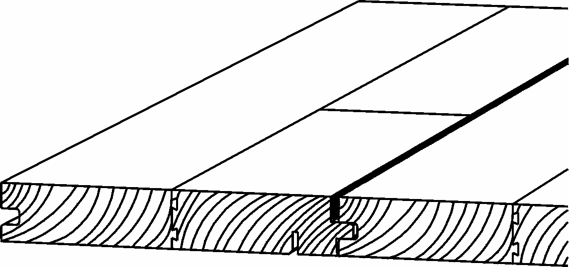
Fig. 1, Ships decking floorboard
FLOORBOARDS ABOVE FLOOR HEATING
Wood is a living material. Wood will contract when heated from an underfloor heating system and during the heating season larger board gaps than normal will form between the boards. The floor temperature under e.g. low bookcases and carpets with good heat insulation properties will be higher than for the rest of the floor, so that larger gaps can be expected in these areas. Junckers Ships Decking is particularly suitable for laying over underfloor heating since the joint absorbs movement in the floor surface and thereby prevents gaps forming, see Fig. 1.
Floor laying can begin when the relative humidity (RH) in the building is within the relative humidity range expected in the building when in use. The normal RH of residential buildings is in the range 35-65 % RH, see also C 1.0.
INTERMEDIATE LAYER
In structures with heat-distribution plates floor cardboard, 500 g/m², is used as an intermediate layer to avoid noise from movement between floorboards and heatdistribution plates.
LOAD BEARING STRENGTH
The load bearing strength of the floor structure must be capable of supporting the actual load.
THERMAL CONDUCTIVITY, [W/m°K]
Beech, Oak, Ash and Maple: Approx. 0.17
Fig. 2
------------------------------------------------------
THERMAL RESISTANCE, md [m² °K/W]
22 mm floorboards: 0.13
20.5 mm floorboards: 0.12
15 mm floorboards: 0.09
14 mm floorboards: 0.08
Intermediate layer:
Junckers PolyFoam, incl. extra 0.20 mm
PE membrane: 0.07
Junckers Foam: 0.04
Floor cardboard, 500 g/m²: 0.01
Junckers 10 mm Sportsfoam: 0.26
Load-distribution boards:
3 mm hardwood fibre board: 0.02
10 mm chipboard: 0.09
Fig. 3
----------------------------------------------------
TERMINOLGY
Maximum output [W/m²]
The maximum amount of energy, in watts per m² which radiates from the surface of the floor.
Maximum surface temperature, floorboards [°C]
The maximum permitted temperature on the surface of the floorboards.
Flow temperature [°C]
The temperature of the water flowing from the boiler to the heating circuit under the floor. The flow temperature required to give a floorboard surface temperature of e.g. 27 °C depends on the type of floor heating system, the floor structure and the floor covering. The flow temperature will normally lie between 35 and 45 °C.
Thermal conductivity, [W/m°K]
Expresses the ability of the material to conduct heat, see Fig. 2.
Thermal resistance [m² °C/W]
The thermal resistance of a material is calculated on the basis of the thickness of the material divided by its thermal conductivity. The total thermal conductivity of a structure, e.g. a floor system, comprising boards and intermediate layer, is the sum, ( md), of the heat resistance in boards and intermediate layer, see Fig. 3.
Example: 14 mm clip system laid on PolyFoam, the total insulation is: md = 0.08 + 0.07 = 0.15 m² °K/W.
HEAT LOSS
Below are shown indicative temperature differences, ∆T, for the individual floor thicknesses, based on an output of 70 W/m², and normal operating output of 50 W/m².
Output: 70W/m²: ∆T [°C]:
22 mm floorboards: +9
20.5 mm floorboards: +8
14 mm floorboards: +6
Output: 50W/m²: ∆T [°C]:
22 mm floorboards: +6
20.5 mm floorboards: +6
14 mm floorboards: +4
Fig. 4
----------------------------------------------
Heat loss through floorboards, ∆T [°C]
Depending on the thermal resistance of the floor covering and the actual power output the temperature will rise down through the floor structure from the surface of the floor covering, see Fig. 4.
Example: With a surface temperature on the boards of 27 °C and output 70 W/m², the surface temperature of the concrete for a 14 mm clip system laid on PolyFoam can be calculated as: 27 + ( md x 70) = 37.5 °C, where ∑md = 0.15 m² °K/W.